[T8200PRO] Communication function (option) setting method
The T8200PRO can inspect resonance characteristics and read the ID by communication by using an antenna for both resonance frequency inspection and communication inspection (sold separately). Here, we will explain the wiring method and software setting method for performing communication inspection (ID reading).
Please also refer to the setting method of [T8200PRO] resonance characteristic inspection by transmission and resonance characteristic inspection by reflection.
Please also refer to the setting method of [T8200PRO] resonance characteristic inspection by transmission and resonance characteristic inspection by reflection.
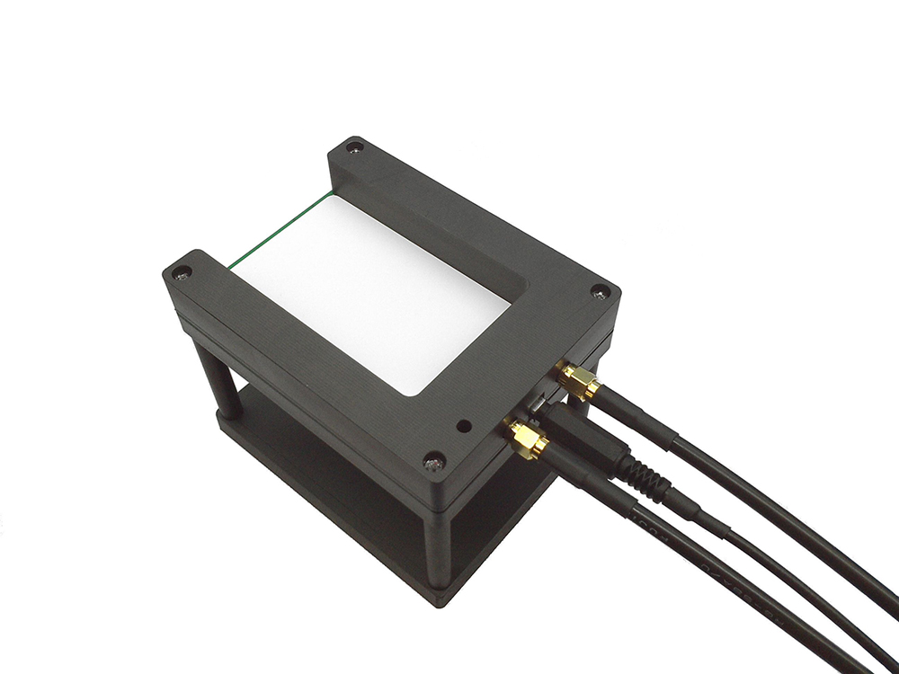
Fig. 1 Antenna for both resonance frequency inspection and communication inspection (sold separately)
Wiring
Transparency characteristics and communication inspection
(1) Connect the HF output terminal of the main unit and the transmitting terminal of the antenna with a coaxial cable.
(2) Connect the input terminal of the main unit and the receiving terminal of the antenna with a coaxial cable.
(3) Main unit Connect the control terminal of this unit and the control terminal of the antenna with the attached cable (3.5 mm plug).
(2) Connect the input terminal of the main unit and the receiving terminal of the antenna with a coaxial cable.
(3) Main unit Connect the control terminal of this unit and the control terminal of the antenna with the attached cable (3.5 mm plug).
* Please note that the SMA terminal of the inspection probe has a distinction between the input side and the output side.
Fig. 2 Wiring method (resonance characteristic inspection by transmission)
Reflection characteristics and communication inspection
(1) Connect the HF output terminal of the main unit and the transmitting terminal of the antenna with a coaxial cable.
(2) Connect the input terminal of the main unit and the receiving terminal of the antenna with a coaxial cable.
(3) Connect the control terminal of the main unit and the control terminal of the antenna with the attached cable (3.5 mm plug).
(2) Connect the input terminal of the main unit and the receiving terminal of the antenna with a coaxial cable.
(3) Connect the control terminal of the main unit and the control terminal of the antenna with the attached cable (3.5 mm plug).
* Please note that the SMA terminal of the inspection probe has a distinction between the input side and the output side.
Fig. 3 Wiring method (resonance characteristic inspection by reflection)
Inspection software settings
In the inspection software settings, you can select the power (Normal Power / Low Power) during communication, enable / disable the communication function, and select the communication protocol.
(1) Select [System Settings / Maintenance] from the top menu.
(2) Select "Normal Power" for "Power setting for communication function" in the [System setting / maintenance] menu. Click the [Close] button to close this screen.
(3) Select [Category file settings] from the top menu.
(4) Check "Communication function enabled" on the "Judgment" tab and select "Card / Tag Type". If you want to make a PASS / FAIL judgment depending on whether the ID can be read, check "Pass / Fail Judgment".
(5) Click the [Finish Settings] button to close this screen.
Figure 4 Inspection software settings
Inspection results
The communication result is displayed below the resonance frequency (lower right of the screen).
If communication does not work
If the ID cannot be read by communication
・ Is the wiring wrong?
-Is the protocol setting incorrect?
Please confirm. Communication may not be possible depending on the electrical characteristics of the inspection card and the distance between the antenna and the card. In that case, try settings 2 to 4 in Table 1.
・ Is the wiring wrong?
-Is the protocol setting incorrect?
Please confirm. Communication may not be possible depending on the electrical characteristics of the inspection card and the distance between the antenna and the card. In that case, try settings 2 to 4 in Table 1.
table 1
|
Control terminal cable
|
System setting / maintenance Power setting for communication function
|
|
|
Setting 1 (standard setting)
|
Connecting
|
Normal Power
|
|
Setting 2
|
Not connect
|
Normal Power
|
|
Setting 3
|
Connecting
|
Low Power
|
|
Setting 4
|
Not connect
|
Low Power
|