[T8200PRO] How to set resonance characteristic inspection by transmission and resonance characterist
The T8200PRO can inspect the resonance characteristics by transmission or the resonance characteristics by reflection. This page explains how to connect each inspection and how to set the inspection software.
Resonance characteristic inspection by transmission
In "transmission inspection", the sine wave signal output from the T8200PRO main unit is applied to the inspection target, and the transmitted (through) voltage is measured.
Wiring
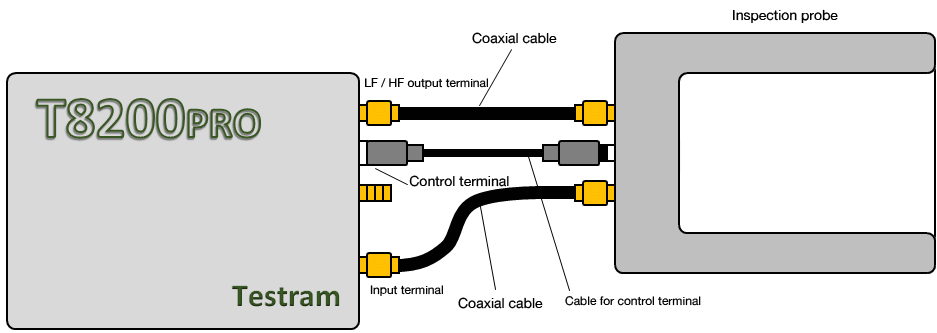
- Connect the T8200PRO main unit and the inspection probe as shown in Figure 1.
- Please note that the SMA terminal of the inspection probe has a distinction between the input side and the output side.
* If you do not perform communication inspection, you do not need a cable for control terminals.
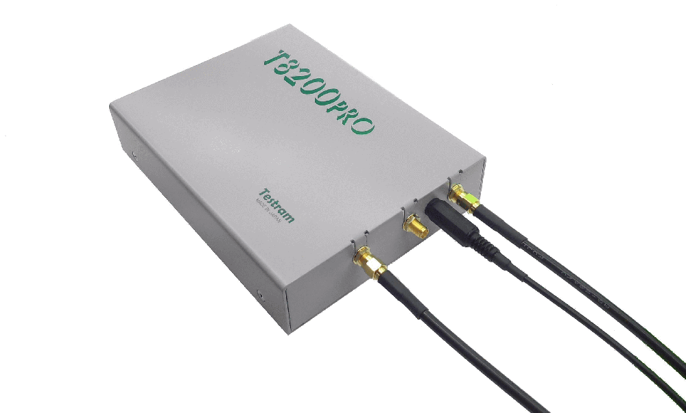
|
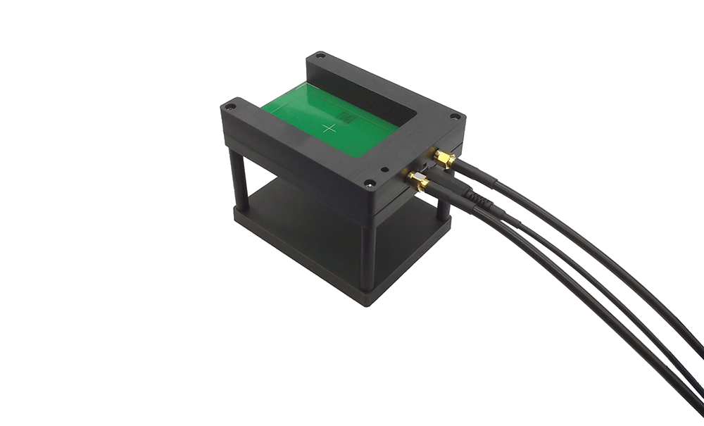
|
Fig. 1 Wiring method (resonance characteristic inspection by transmission)
Inspection software settings
(1) Select [Category file settings] from the top menu.
(2) Select "Through characteristics" in the LF and HF band connection modes on the [Category file settings] screen.
(3) Select "Judgment" tab, sideband width determination method "A", and set α: 3dB.* Please note that this is different from the case of reflection.
(4) Click the [Finish Settings] or [Calibrate] button to close the dialog.
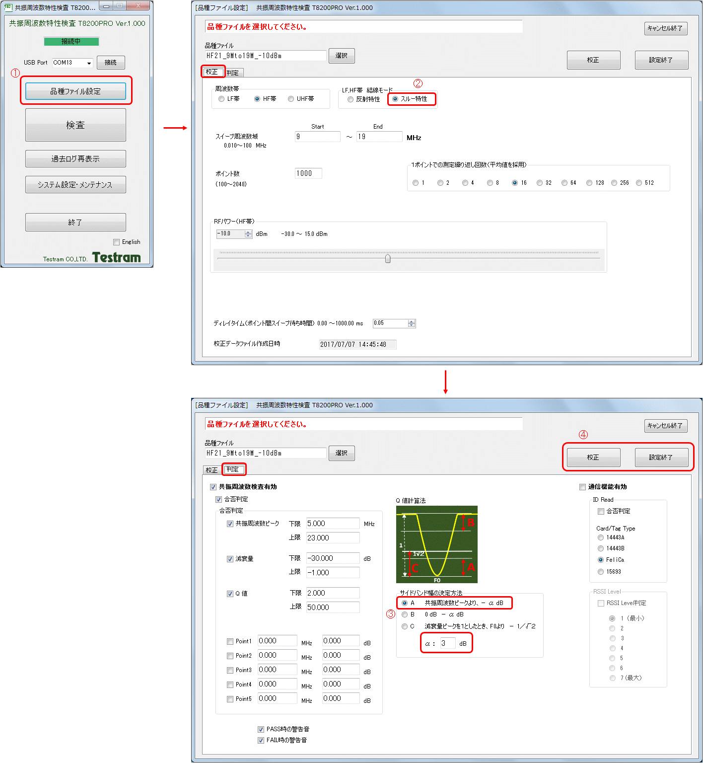
Fig. 2 Inspection software setting (resonance characteristic inspection by transmission)
Resonance characteristic inspection by reflection
In "reflection inspection", the sinusoidal signal output from the T8200PRO main unit is applied to the inspection target and the reflected voltage is measured.
Wiring
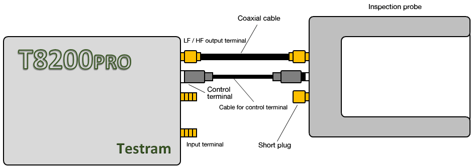
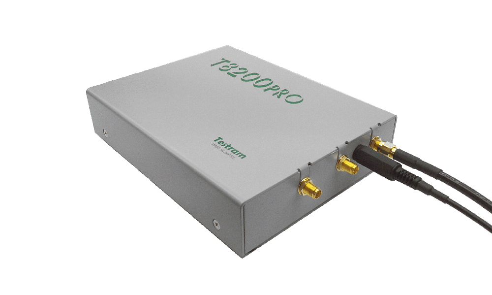
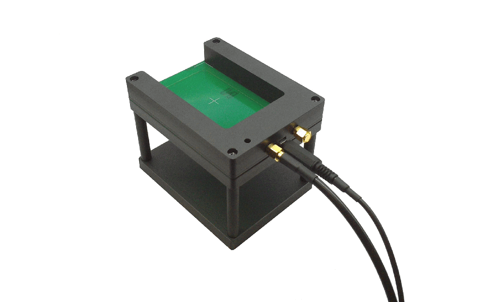
- Connect the T8200PRO main unit and the inspection probe as shown in Fig. 3.
- Please note that the SMA terminal of the inspection probe has a distinction between the input side and the output side.
- Connect the short plug to the SMA terminal of the inspection probe that is not connected to the T8200PRO.
* If you do not perform communication inspection, you do not need a cable for control terminals.
|
|
Fig. 3 Wiring method (resonance characteristic inspection by reflection)
Inspection software settings
(1) Select [Category file settings] from the top menu.
(2) Select "Reflection characteristics" in the LF and HF band connection modes on the [Category file settings] screen.
(3) Select "Judgment" tab, sideband width determination method "B", and set α: 3dB.* Please note that it is different from the case of transparency.
(4) Click the [Finish Settings] or [Calibrate] button to close the dialog.
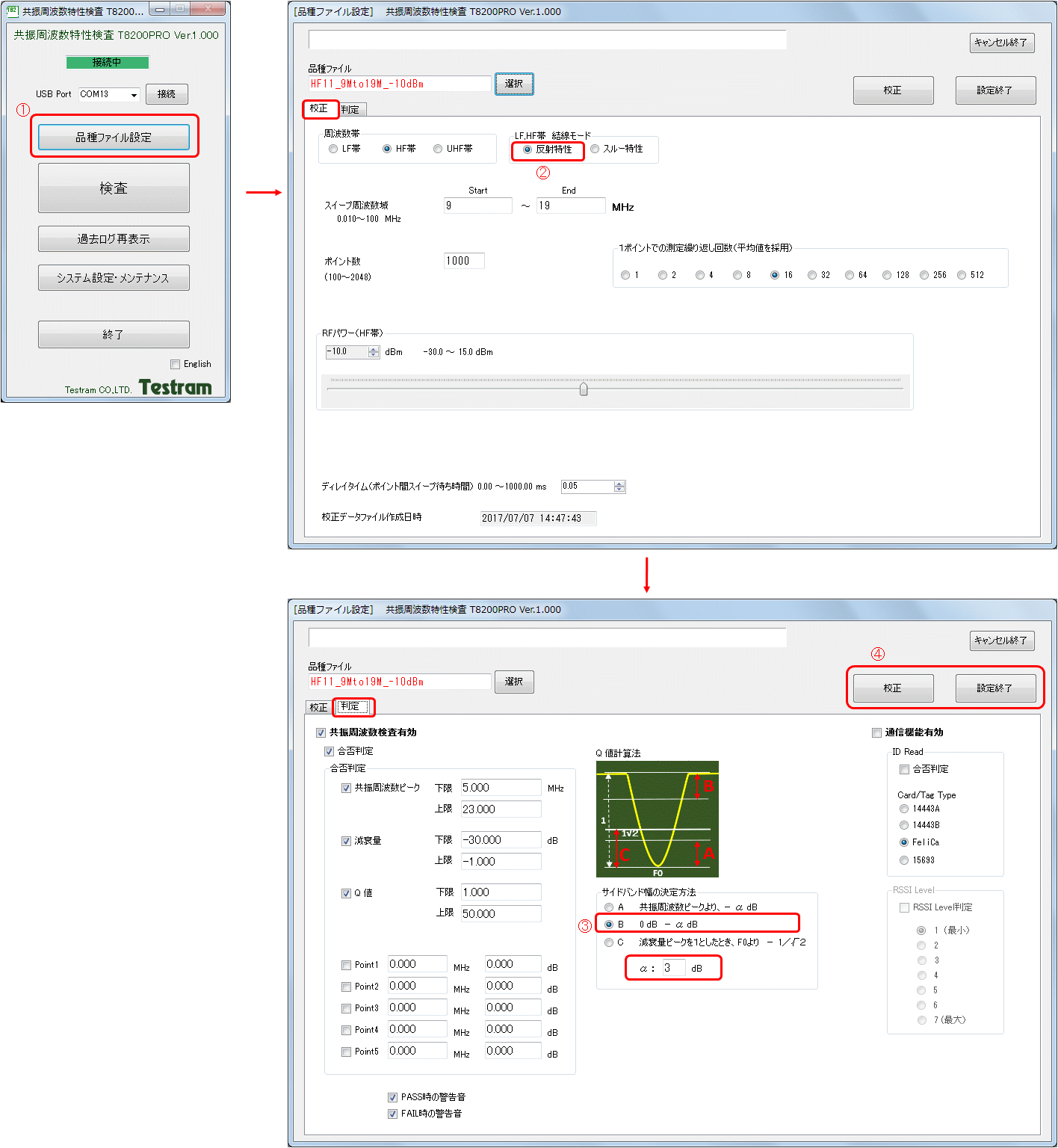
Fig. 4 Inspection software setting (resonance characteristic inspection by reflection)
